Windings
Command: pre_models(“Gen_winding”)
Automatic winding scripts are usually used with a parameter-based model.
Example:
m.tot_num_slot   =      12.00    --  Total Number of slots
m.num_poles      =       4.00    --  Number of Poles 2p
m.num_phases     =       3.00    --  Number of Phases m  <= 500
m.num_layers     =       1.00    --  Number of Layers per slot u
m.num_wires      =     100.00    --  Number of wires per slot side
m.current        =      20.00    --  Wdg-Current [A] or flux [Vs/mm]
m.coil_span      =       3.00    --  Coil span   >= 1
m.num_slots      =       3.00    --  No of slots in FE-Model (Rot-Mot)
m.mat_type       =       1.00    --  Ma-type:1=Rot;21=lin-x;22=lin-y
m.wind_type      =       1.00    --  W-typ:1=w&cur;2=w&flux;3=bar&cur
m.win_asym       =       1.00    --  asy. slot pitch: 1=sym.; <1=asym.
m.wdg_location   =       1.00    --  Wdg location: -1: intern 1: stator; 2: rotor
m.curr_inp       =       1.00    --  CURR:Const:0<< Q-axis:1 D-axis:-1

pre_models("Gen_winding")
Command: pre_models(“gen_pocfile”)
Automatic creation of a POC file, which is required for the fast calculation routines run_models (“mult_cal_fast”) (see Multiple Calculation) or run_models (“pm_sym_fast”) (see Simulation PM/Reluctance motor) and defines the current waveform vs. the rotational position.
Typical structure of the POC file of a 3-phase machine with sinusoidal current (see FEMAG-manual):
POC-File     | Comment
-------------+-----------------------------------------------------
3            | No. of phases
1            | Nummer des Wicklungsstranges 1
2            | Nummer des Wicklungsstranges 2
3            | Nummer des Wicklungsstranges 3
30.000000    | Zero-crossing angle of the EMF in phase 1
150.00000    | Zero-crossing angle of the EMF in phase 2
270.00000    | Zero-crossing angle of the EMF in phase 3
180.00000    | Mechanical rotation angle of 1 electrical period
sin          | Current waveform type
0.0000000    | Schrägungswinkel (Phase-shift angle?)
0            | Anzahl von Schrägungsstufen (No. of phase-shifts?)
Note
Automatic creation of the POC file for rotating machines is currently possible only in the polar coordinate system (cosys(polar)).
End-winding distribution and end-turn length
The following commands can be used to define the approximate shape of the end-winding. This data is used to estimate the end-winding self- and mutual-inductance components for the individual coils. These inductances are combined into the d- and q-axis inductances. (“Eigen-und Gegeninduktivitäts-Anteile des Wickelkopfes”)
The end-winding shape definition is also used to estimate the relative end-winding length. The resulting end-winding length is used to adjust the relative conductor length. When the armature length (arm_length) > 1mm, end-winding length is added to it and related to the armature length.
culength = (arm_length+end_winding_length)/arm_length
If the armature length has not been defined (arm_length = 1mm), the relative end-winding length is related to a fictitious armature length of 100 mm.
culength = (100mm+end_winding_length)/100mm
The relative winding length can be obtained at any time with the command
rl1,rl2 = get_dev_data ( "cond_rel_length" )
and it can be adjusted. (See get_dev_data).
Available end-winding definitions
Command: pre_models(“leak_tooth_wind”)
Calculate the leakage inductance of a single-tooth winding.
cCall: leak_tooth_wind
Example for the input:
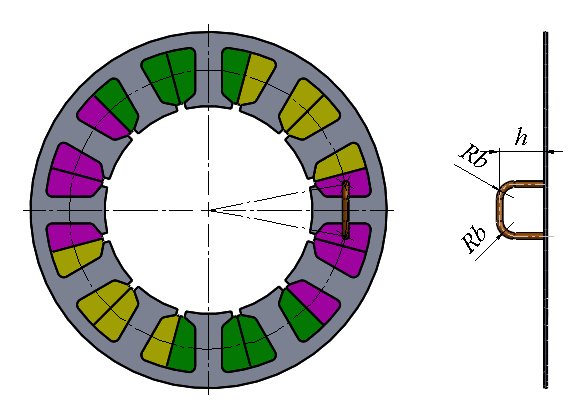
m.nseg            =          2.000  -- Number of segments
m.npolsim         =          5.000  -- Number of poles simulated
m.fc_radius       =         34.250  -- Radius air-gap center (torque) [mm]
m.arm_length      =        100.000  -- Effect. armature length[mm]
m.endheight       =         10.000  -- End winding height h[mm]
m.bendrad         =          4.000  -- Bending radius Rb[mm]
m.wiredia         =          1.000  -- Wire diameter dw[mm]
m.arm_length      =        100.000  -- Effect. armature length[mm]

pre_models("leak_tooth_wind")
Command: pre_models(“leak_dist_wind”)
Calculate the leakage inductance of a distributed winding.
call: leak_dist_wind
Example for the input:
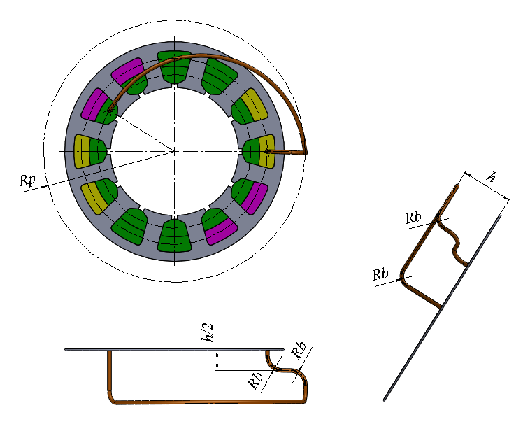
m.nseg            =          2.000  -- Number of segments
m.npolsim         =          2.000  -- Number of poles simulated
m.fc_radius       =         24.900  -- Radius air-gap center (torque) [mm]
m.arm_length      =        100.000  -- Effect. armature length[mm]
m.perimrad        =         44.000  -- Radius of perimeter Rp[mm]
m.vbendrad        =          4.000  -- Bending radius vertical Rb[mm]
m.endheight       =         16.000  -- End winding height h[mm]
m.wiredia         =          0.560  -- Wire diameter dw[mm]

pre_models("leak_dist_wind")
Command: pre_models(“leak_evol_wind”)
Calculate the leakage inductance of an involute winding.
call: leak_evol_wind
Example for the input:
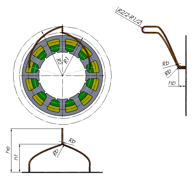
m.nseg            =          2.000  -- Number of segments
m.npolsim         =          2.000  -- Number of poles simulated
m.fc_radius       =         24.500  -- Radius air-gap center (torque) [mm]
m.arm_length      =        100.000  -- Effect. armature length[mm]
m.evol1rad        =         29.880  -- Top radius of first evolvent R1[mm]
m.evol2rad        =         35.856  -- Top radius of second evolvent R2[mm]
m.botlevel        =         20.000  -- Level at bottom of evolvents hb[mm]
m.toplevel        =         60.000  -- Level at top of evolvents ht[mm]
m.endheight       =         80.000  -- End winding height he[mm]
m.evolbend        =          2.000  -- Bending radius Rb[mm]
m.wiredia         =          1.000  -- Wire diameter dw[mm]

pre_models("leak_evol_wind")